DEM
Note
Here we assume that the DEM file only includes the three-dimensional coordinates of points. The input format for the DEM is a three-column array, where the first column represents the x-coordinate, the second column represents the corresponding y-coordinate, and the third column is the z-coordinate.
The Digital Elevation Model (DEM) is a special 3D case. Typically, for landslide simulations, we obtain a DEM file composed of surface data, which consists of three-dimensional scatter points, with each x-y coordinate corresponding to a unique z value. Before generating the material points, we need to perform a simple processing step by rasterizing it on the x-y plane using inverse distance weighting (IDW). We then proceed to generate the material points based on our requirements.
DEM file pre-processing
The DEM file is a simple three-column array. Each DEM must be rasterized to ensure it is structured (regular) in the x-y plane.
MaterialPointGenerator.rasterizeDEM Method
rasterizeDEM(dem, h; k=10, p=2, trimbounds=[0.0 0.0], dembounds=[0.0, 0.0])Description:
Rasterize the DEM file to generate particles.
demis a coordinates Array with three columns(x, y, z)his the space of the cloud points inxandydirections, normally it is equal to
the grid size in the MPM simulation.
[optional]:
kis the number of nearest neighbors (10 by default)pis the power parameter (2 by default)trimboundsis the boundary of the particles, which is a N*2 array, each row is a vertex
of the polygon
demboundsis the rectangle boundary of the DEM, which is [xmin, xmax, ymin, ymax]
Through this function, we can rasterize the input DEM file and specify the spacing between each point (which is the same as the grid size in the MPM simulation). The trimbounds parameter is used to define the shape of the DEM file in the x-y plane; it is a two-dimensional array where each row represents a vertex of the shape in the x-y plane. The dembounds parameter can be used to specify the range of the DEM in the x-y plane; it is a vector that represents [xmin, xmax, ymin, ymax]. This can be utilized to process two DEMs of the same area at different times, ensuring they have completely consistent x-y coordinates.
DEM with a flat bottom surface
Suppose we have a DEM and we want to close it with a base plane, for example, at z=0.
MaterialPointGenerator.dem2particle Method
dem2particle(dem, h, bottom)Description:
Generate particles from a given DEM file. dem is a coordinates Array with three columns (x, y, z). h is the space of particles in z direction, normally it is equal to the grid size in the MPM simulation. bottom is a value, which means the plane z = bottom.
DEM with a given bottom surface
If the base used to close DEM-1 is not a flat surface, we can designate another DEM-2 to serve as the base for closing DEM-1.
MaterialPointGenerator.dem2particle Method
dem2particle(dem, h, bottom)Description:
Generate particles from a given DEM file and a bottom surface file. dem is a coordinates Array with three columns (x, y, z), which has to be initialized with the struct DEMSurface. bottom::DEMSurface should have the same x and y coordinates as the DEM, and the z value should be lower than the dem. h is the space of grid size in z direction used in the MPM simulation.
Info
DEM-2 and DEM-1 should have exactly the same coordinates in the x-y plane. This can be achieved using rasterizeDEM.
Advanced
Here, we consider attaching geological structures (material properties) to the filled material points. The output of this workflow consists of two files: the first, as before, is a 3D scatter coordinate file in .xyz format, and the second is a material ID file (.nid) with the same number of points as the scatter file.
To prepare for this, you need to have layered surface files in DEM format, which should have exactly the same x-y coordinates as the input DEM surface file (this can be achieved using parameters a and b). They should look like the following:
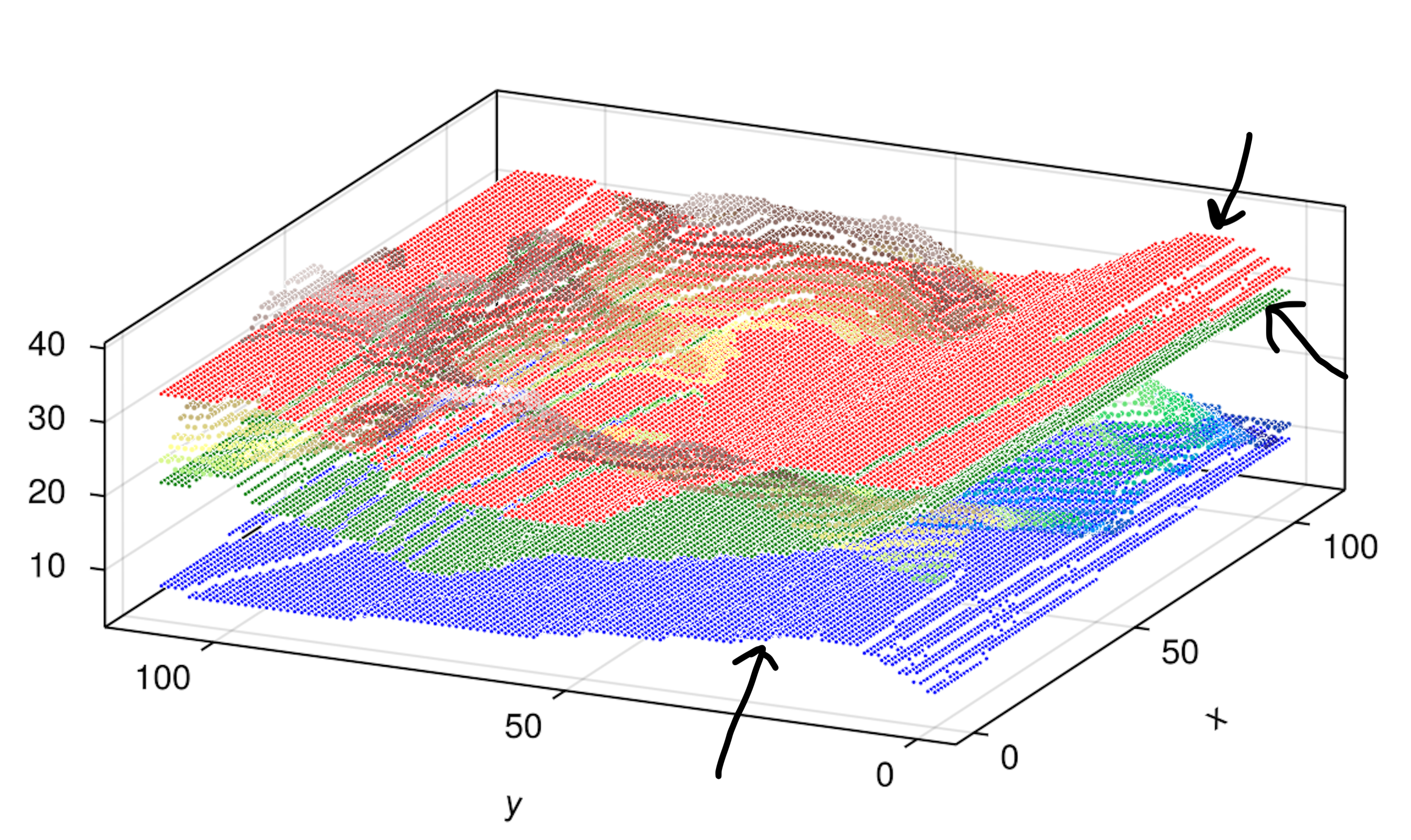
MaterialPointGenerator.dem2particle Method
dem2particle(dem, h, bottom, layer)Description:
Generate particles from a given DEM file and a bottom value (flat bottom surface). dem is a coordinates Array with three columns (x, y, z), and the bottom value should be lower than the dem. h is the space of grid size in z direction used in the MPM simulation. layer is a Vector of Matrix with three columns (x, y, z), which represents the layer surfaces. Note that layers are sorted from top to bottom.
Assuming that we have processed each layered DEM(s), they should be saved in the layer Vector in order from top to bottom along the z-direction as input. Please refer to the usage in the Example section.
This workflow also supports the case where a bottom DEM is provided:
MaterialPointGenerator.dem2particle Method
dem2particle(dem, h, bottom, layer)Description:
Generate particles from a given DEM file and a bottom surface file. dem is a coordinates Array with three columns (x, y, z), and the z value should be lower than the dem. h is the space of grid size in z direction used in the MPM simulation. layer is a Vector of Matrix with three columns (x, y, z), which represents the layer surfaces. Note that layers are sorted from top to bottom.